SAPIN3 : 3 Input Serial Converter
Embedded Micro Software
8/8/00


![]()
Introduction
The software is written in C using the CCS PCM C Compiler which is a powerful and cost effective compiler.
Hardware
Description

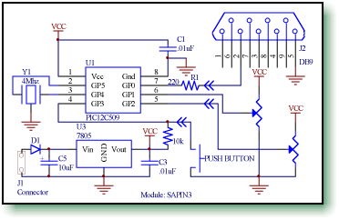
The 2 a/d inputs are applied to GP1 and GP2. The potentiometers shown are external and provide a 0 to 5 volt input. The single digital input is a pushbutton switch connected to pin 4 (GP3) and pulled up to VCC with a 10k resistor.
The 5 volts to power the module is provided by the 7805 type regulator.
Software
Description
//------------------------------------------------


      // file:   sapin3.c


      // author: Emicros


      // update: 8/8/00


      //------------------------------------------------


      // Description: This file contains the C source


      // code for a PIC12C672 to read 2 a/d inputs


      //              and 1 digital input and send the


      //              data at 9600 baud to a terminal (PC).


      //


      // Compiler:    CCS PCM C Compiler


      // Compiling:   pcm -c sapin3.c


      //------------------------------------------------


      #include <12c672.h>


      #use delay(clock=4000000)


      #use rs232(baud=9600,xmit=PIN_A0,INVERT)


      //--------------------------------------


      // Period of time between updates


      //--------------------------------------


      #define REPEAT_TIME 100


      unsigned int rad1, rad2;
while( 1 )
{
execute program forever
}
The a/d channels are set as inputs in the set_tris_a statement followed by the statement that controls the delay between sends. The REPEAT_TIME is defined in the header portion of the file and is set to 100 milliseconds.
//-----------------------------------------------


      // function: main()


      //-----------------------------------------------


      void main( void )


      {


        while( 1 )


        {


          //----------------------------


          // setup the processor. Note


          // the delay statement.


          //----------------------------


          set_tris_a( 0x1f );


          delay_ms( REPEAT_TIME );


          setup_adc( ADC_CLOCK_DIV_8 );


          setup_adc_ports( ALL_ANALOG );


          //----------------------------


          // read the a/d channels


          //----------------------------
set_adc_channel( 1 );


          delay_us( 10 );
rad1 = read_adc();


          set_adc_channel( 2 );


          delay_us( 10 );
rad2 = read_adc();


          setup_adc_ports( NO_ANALOGS );


          //----------------------------


          // display the a/d channels


          //----------------------------


          printf( "ad1=%u,", rad1 );


          printf( "ad2=%u,", rad2 );


          //----------------------------


          // display the digital input


          //----------------------------


          if( input( PIN_A3 ) )


            printf( "1" );


          else


            printf( "0" );


          printf( "\n\r" );


        }


      }
The clock used for the a/d conversion is set to the divide by 8 configuration. This allows correct conversion using the 4 Mhz oscillator. Refer to the data sheet for more details. The a/d pin configuration is then set for all analog configuration.
A/D channels 1 and 2 on pins 6 (GP1) and 5 (GP2) are converted and storied in variables rad1 and rad2 respectively. These are 8 bit values ranging from 0 to 255 (0 to 0xff hex).
The remaining portion of the while loop uses the printf statement to format the output as ascii text. The printf statement sends the text out the serial channel.
Software
Compiling
The software for the PIC is written in C for the CCS PCM C Compiler. The program is compiled from the DOS command prompt as;
pcm -c sapin3.c
Programming
- Oscillator: HS
- Power Up Timer: Off
- Code Protect: Off
- Master Clear: Internal